Every decision made at the interface between glass and structure carries consequence. Structural glass floor connection details govern how loads transfer from the walking surface through the framing system and into the primary structure—and they simultaneously determine whether a system can achieve, or forfeit, a fire-resistance rating under the International Building Code. For architects and structural engineers specifying walkable glass in commercial projects, understanding the mechanical and regulatory implications of each connection type is not optional; it is the foundation of a compliant, long-lived installation.
At the broadest level, structural glass floors rely on one of two support philosophies: continuous edge support, where the glass lite is carried along all four edges by a framing system, or point-fixed support, where discrete mechanical fittings transfer load at specific locations on the glass surface or edge. Each approach creates a fundamentally different stress distribution within the laminated glass assembly, and each carries distinct consequences for fire-rating classification.
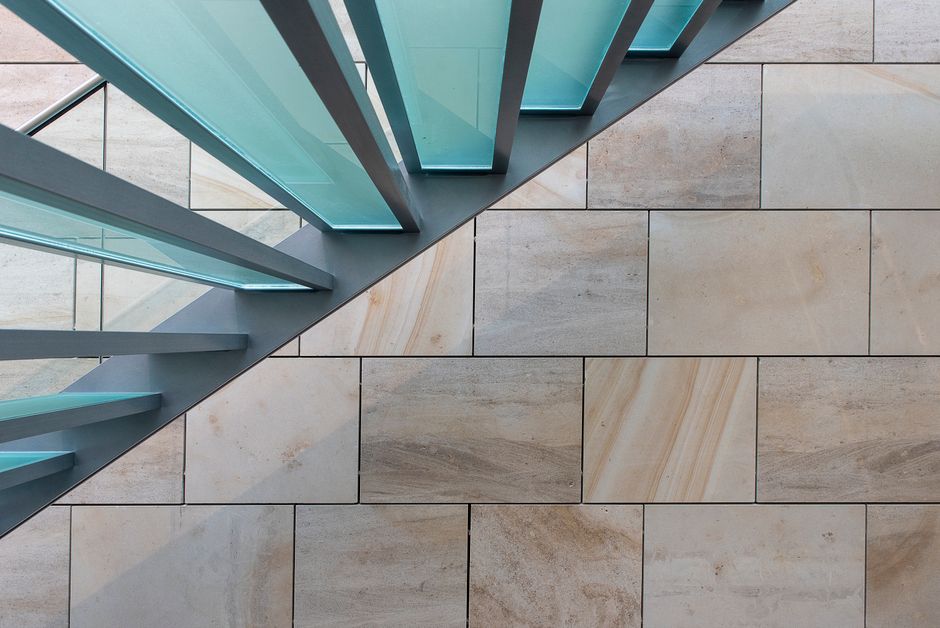
Continuously supported systems remain the dominant configuration for fire-rated glass floor installations in North America, and the reason is straightforward: the closed perimeter frame provides a defined, testable boundary condition that fire-resistance testing protocols can replicate reliably. In a continuously supported assembly, the glass floor panel—typically a multi-ply laminated unit—bears along all four edges against a structural steel or aluminum framing member, usually with a proprietary intumescent or elastomeric setting block and perimeter gasket system interposed between glass and metal.
Glass floor framing systems used in continuously supported configurations must satisfy two demands simultaneously: structural stiffness and thermal performance under fire exposure. Steel framing offers high strength-to-depth ratios and is the standard substrate for fire-rated assemblies tested under ASTM E119 or UL 263, but untreated steel conducts heat efficiently—making intumescent protection or thermally broken details essential when radiation or temperature-rise criteria apply. Aluminum framing, while architecturally cleaner and corrosion-resistant, requires careful engineering at fire-rated conditions because of its comparatively low melting point; most listed fire-rated glass floor systems that incorporate aluminum rely on proprietary thermally broken profiles with embedded intumescent seals that expand under heat to maintain boundary integrity.
Frame depth is a critical variable often underestimated during schematic design. Deflection limits for glass floors are typically held to L/360 of the clear span under live load—more stringent than most structural framing—and the framing member must achieve this stiffness within the floor-to-floor depth available. Early coordination between the architect, structural engineer, and glass floor specialist is essential to avoid late-stage conflicts with mechanical and electrical clearances below the system.
Perimeter edge support design must provide adequate glass bite—the dimension by which the frame overlaps the glass edge—to ensure load transfer without overstressing the glass at the bearing zone. Industry practice for structural glass floors typically calls for a minimum bite of 25 mm (approximately 1 inch), though project-specific engineering and the glass manufacturer's recommendations govern. Setting blocks must be positioned to prevent glass-to-metal contact while maintaining the glass panel in its correct plane; for fire-rated assemblies, setting block material must be verified for compatibility with the listed system, as substitutions can void the fire-resistance classification.
For a comprehensive look at how these variables interact with IBC occupancy and rating requirements, the fire-rated glass floor IBC compliance specification guide provides detailed code mapping that complements the connection-level detail discussion here.
Point-fixed glass floors use discrete mechanical fittings—spider fittings, countersunk bolt fixings, or proprietary patch fittings—to transfer load from the glass into the supporting structure at three, four, or more discrete locations per panel. The architectural appeal is significant: continuous framing members are minimized or eliminated, creating the impression of glass unsupported in space. However, the structural and regulatory trade-offs are equally significant.
When load is transferred at discrete points rather than distributed along a continuous edge, bending stress in the glass concentrates around each fixing location. The glass must be engineered to resist this stress concentration through increased thickness, additional laminate plies, or both. A countersunk bolt fixing introduces a hole through the glass, which creates a stress raiser; engineering these details requires finite element analysis or validated analytical methods that go beyond standard beam-on-elastic-foundation models used for continuously supported panels. The hole diameter, countersink geometry, bolt material, and the compliance of the load transfer bushing all influence the peak stress and must be coordinated with the glass fabricator's structural calculations.
Here is where point-fixed systems create their most significant regulatory challenge: achieving a listed fire-resistance rating with a point-fixed structural glass floor assembly is extremely difficult under current IBC and ASTM testing frameworks. Fire-resistance ratings are assigned to assemblies as tested—not to individual components. A point-fixed system represents a fundamentally different boundary condition than the continuously framed assemblies on which nearly all listed fire-rated glass floor products are tested. Unless a manufacturer has conducted full-scale fire-resistance testing of a specific point-fixed configuration and obtained a listing from an accredited laboratory, a point-fixed glass floor cannot be specified as a fire-rated assembly under IBC Section 712 (walking surfaces of glass).
This distinction matters enormously in occupancies where the IBC mandates fire-rated floor construction—particularly in buildings of Type I or II construction where floor assemblies must achieve one- or two-hour ratings. Architects who design point-fixed glass floors in these occupancies without verifying fire-rating eligibility risk a code compliance failure that cannot be remediated without replacing the system. Understanding common misconceptions about what constitutes a compliant fire-rated glass floor is covered in depth in the article on 4 myths about fire-rated glass floors—required reading before finalizing any connection strategy.
Regardless of whether a continuously supported or point-fixed framing strategy is chosen, the laminated glass floor assembly itself must be engineered for the specific connection type. A fire-rated laminated glass floor assembly typically comprises multiple glass plies—often combinations of tempered and heat-strengthened glass—bonded with one or more interlayer types that serve distinct structural and fire-resistance functions.
Structural interlayers such as SentryGlas ionoplast provide meaningfully higher shear stiffness than standard PVB, which allows the composite laminate to achieve greater effective thickness and reduced deflection under load. For fire-rated assemblies, the interlayer system must also contribute to the fire-resistance mechanism—in many listed systems, a clear intumescent interlayer is incorporated between glass plies to absorb heat energy, limit temperature rise on the unexposed face, and maintain panel integrity during the fire exposure period. The fire-rated interlayer must be specified from the tested and listed assembly; field substitution is not permissible.
Laminated glass floor assembly details must address panel aspect ratio, as highly elongated panels (aspect ratios exceeding 3:1) develop disproportionately higher bending stresses along the short span and may require thicker assemblies or intermediate support. Deflection under combined dead and live load must be evaluated at both the panel level and the framing level; frame deflection adds to glass deflection and must be included in total system deflection calculations. The fire-rated glass floor load calculations guide for structural engineers addresses these combined deflection scenarios with worked examples relevant to commercial live load conditions.
Connection details that perform structurally on day one must also accommodate thermal movement, long-term creep in interlayer materials, and maintenance access over a building's service life. Perimeter gaskets and setting blocks should be specified with documented service life data. Bolt fixings in point-fixed systems require periodic inspection and torque verification. Drainage paths must be maintained in framed systems to prevent water infiltration that could compromise interlayer adhesion over time.
For fire-rated assemblies, the connection detail must also be documented as part of the project's listed assembly record—including the specific framing manufacturer, glass fabricator, interlayer type, and hardware. Any field modification that deviates from the tested assembly must be reviewed and approved by the testing laboratory or the authority having jurisdiction before installation proceeds.
Getting structural glass floor connection details right requires integrating structural engineering, fire-resistance testing knowledge, and fabrication expertise from the earliest phases of design. LITEFLAM's team of glass floor specialists works directly with architects and structural engineers to develop connection details that meet both performance and code requirements from the outset. Contact LITEFLAM to discuss your project's specific framing system, fire-rating requirements, and connection design strategy with a specialist who has executed these details across some of North America's most demanding commercial installations.